PAM Motors

General Information
Pole – Amplitude – Modulation
PAM Two-Speed Technology
For decades, Westinghouse PAM Motors have helped industries and utilities around the world improve operating economies.
In fact, TECO-Westinghouse has more Pole Amplitude Modulation (PAM) Motor experience than all of our competitors combined.
Today, our PAM Motors continue to be an innovative solution that offers a wide range of benefits for your controlled-flow applications.
PAM Motors are durable, reliable, and cost-effective – often with a payback period of a year or less.
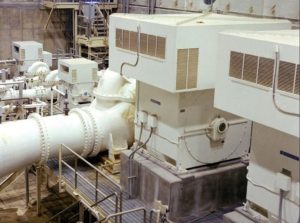
PAM Motors are single-winding, two-speed, squirrel cage induction motors. These motors have the ability to operate at two fixed pole speeds.
This availability of many single winding two-speed combinations gives the PAM motor a much wider range of application than that of conventional single-winding, two-speed motors, where the ratio of one speed to the other must always be two to one.
PAM Speed Switching
The most widely accepted speed changing device for the PAM Motor is the oil-filled, five pole, motor-operated speed-changing switch.
It is typically installed close to the motor to minimize cable requirements. There are six leads (three for each speed) from the switch to the motor.
The PAM Motor is usually started on its lower speed winding to keep the inrush current low. This prolongs motor life by keeping rotor and core temperature excursions to a minimum. Starting on the lower speed is also more desirable for driven equipment considerations.
PAM Application Analysis – ID Fan Design Example
Scrubber Additions and Booster Fans
Today, more than ever, you must consider energy efficiencies when installing new machinery. The PAM Motor design enables you to save a significant amount of energy by switching to an optimum low speed when high-speed operation is not required.
The chart below, of a typical ID fan, Illustrates how a reduction in motor operating speed will in turn reduce horsepower. This lowers the motor’s energy consumption and increases your dollar savings.
By observing the fan laws we see that:
- Volume varies with speed.
- Static pressure varies as the speed squared.
- HP varies as the speed cubed.
In this example, changing speeds results in saving 1200HP. If energy is evaluated at $1700/KW x 1200HP x .746KW/HP, the savings are $1,521,840.
In this example, to attain high unit availability, the fundamental requirement is to size the ID fan such that the boiler will not become ID fan limited. Yet, care is taken not to increase the potential for problems with draft controllability and implosion because of over-sizing. Sufficient margin is added to the gas flow rate estimated from the boiler manufacturer’s predicted MCR heat input so that the ID fans can handle the gas flow at the maximum demonstrated heat input without difficulty.
Additional margins are provided for increased air leakages, boiler gas path fouling, air-heater fouling, fan performance deterioration, and other uncertainties.
To account for all these allowances, typically a 15% mass flow margin and a 32% static pressure margin is applied to the MCR values to obtain the Test Block conditions.
Some fans are specified to be designed for initial base load operation with provisions for future cyclical duty. Additional revised design conditions due to scrubber and balanced draft conversion affect the ID fan size.
These requirements are shown in the Pressure / HP vs. Volume curve.
Thus the fans and motors are designed for Test Block requirements but normal operation is a MCR. This sets the stage for two-speed conditions.